1-4. Quantum circuit diagram
In this chapter, we have learned how to represent qubits and operations. Finally, let us summarize quantum circuit diagrams that describe quantum operations. Just as there are certain rules and symbols for diagrams of logic and electric circuits, there is some standardized notation for quantum circuits.
A quantum circuit diagram generally looks like the following.
The main components are
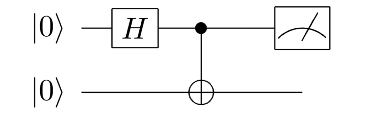
Quantum bits: Each horizontal line in the schematic corresponds to one qubit. The leftmost \(|0\rangle\) means that each qubit is initialized to \(|0\rangle\).
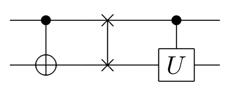
Quantum gates: The boxes and vertical lines in the schematic represent quantum gates. In general, an \(n\)-qubit gate is represented by a box spanning the \(n\) qubits (horizontal lines) on which the gate act. In addition, there are several other gates that are represented in a special written form, such as control NOT gates, SWAP gates, and control \(U\) operations \(\Lambda(U) = |0\rangle \langle 0| \otimes I + |1\rangle \langle 1| \otimes U\) . They are represented as follows.
Measurement: the meter-like symbol on the far right represents taking a measurement for a qubit.
The most important aspect of schematic reading is that schematics are read left to right. In other words, the calculations proceed by performing the quantum gate and measurement operations from left to right, just like a musical score. Thus, the circuit at the beginning means creating the state below
,and then measuring the first qubit.
(see Frequently used quantum gates and circuit symbols in Nomenclature and notation at the beginning of Nielsen-Chuang for details.)